 English
 中文简体
 русский
 Français
 Español
 عربى
Ask anyone who has rewound a motor after a long, hot season and the story is usually the same: the winding failed, but the heat did the damage. Electric motor thermal management is the quiet part of machine design that decides how long that story takes to repeat — and in our experience since 1997, it is settled long before the first lamination is stacked.
Heat is not an accident in an electric machine. It is the unavoidable companion of every loss in the energy conversion chain. A motor that runs twenty degrees hotter than it needs to will not fail tomorrow; it fails two summers later, usually in the middle of a busy production run, and the post-mortem points at insulation that quietly baked itself brittle. The good news is that thermal behaviour is predictable, measurable, and — most of the time — improvable without redesigning the whole machine.
Where the Heat Actually Comes From
Before choosing a cooling method, it helps to know which losses dominate in a given duty point. In most industrial machines the picture looks like this:
- Stator copper loss: the I²R heating in the winding, and usually the largest single contributor at high torque.
- Rotor loss: slip-related losses in induction rotors, and eddy-current heating in permanent magnets on brushless machines.
- Iron loss: hysteresis and eddy losses in the laminations, rising noticeably with supply frequency.
- Mechanical and stray loss: bearings, brush friction, windage, and harmonics that never quite show up in a simple calculation.
The proportions shift with the operating point, and that is where many thermal problems begin. A conveyor, hoist, or warehouse truck working at low speed and high torque produces near-rated copper loss while the shaft-mounted fan is barely turning. The motor is doing its hardest work with its weakest cooling — a classic trap that is far cheaper to design around than to discover in the field.
Insulation Class Is the Real Ceiling
Every thermal discussion eventually lands on the insulation system, because that is what actually fails first. The class letter sets the maximum permitted hotspot temperature, and the standards then translate that into an allowable temperature rise above the reference ambient of 40 °C.
| Insulation class | Maximum hotspot temperature | Typical rise limit |
|---|---|---|
| Class B | 130 °C | 80 K |
| Class F | 155 °C | 105 K |
| Class H | 180 °C | 125 K |
Two practical notes matter more than the table itself. First, resistance measurement gives an average winding temperature, while the end-winding hotspot can sit 10 to 20 K higher — that gap is where insulation ages fastest. Second, many of our customers specify Class F insulation but rate the machine to a Class B rise. That is not waste; it is margin, and margin is what absorbs a blocked fan guard, a dusty summer, or an overloaded conveyor that nobody wants to admit to.
Cooling Paths, from a Shaft Fan to a Water Jacket
Air is still the default for good reason: it is free, it never leaks, and it needs no maintenance schedule of its own. A totally enclosed fan-cooled machine with a well-finned frame handles a large share of industrial duty perfectly well. The limitation is speed dependence — airflow falls roughly with rotational speed, so a motor driven at 30 percent speed by a variable-frequency drive may be receiving a small fraction of its rated cooling.
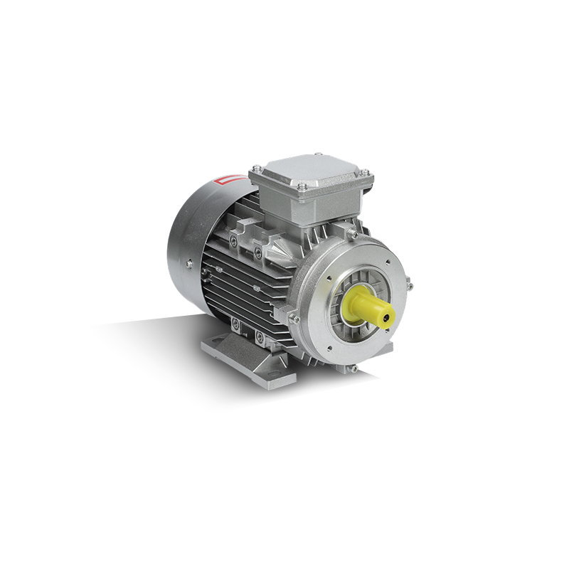
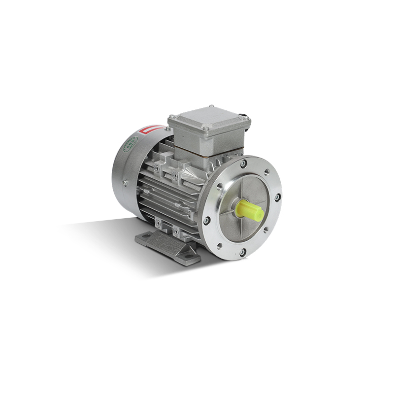 EHBD IE3 Aluminium-Cased Three-Phase MotorAluminium housing supports heat dissipation for variable-speed industrial duty, with IE3 efficiency and 750 W–7.5 kW models.View Product →
Housing material and geometry matter here. An aluminium frame spreads heat away from the stator core far more readily than a comparable cast-iron body, and deeper fins increase the wetted surface without adding a single moving part. Beyond that, the main options are:
- Separate forced ventilation: an independent blower keeps airflow constant regardless of shaft speed, which is the usual fix for inverter duty below base speed.
- Frame conduction: careful stator-to-frame contact, proper interference fits, and thermal interface materials at the mounting face.
- Liquid cooling: water-glycol jackets or oil spray allow much higher power density in a smaller envelope, at the cost of a pump, hoses, coolant quality, and a new set of failure modes.
- Advanced approaches: heat pipes, immersion cooling, and microchannel cooling inside end windings are promising and increasingly discussed, but for most industrial and vehicle installations they remain specialised rather than standard.
Design Details That Decide Winding Temperature
Two motors with identical electrical data can run 15 K apart because of details that never appear on a datasheet. In our manufacturing experience, these are the ones that matter most:
- Slot fill and winding form: more copper in the slot means lower resistance, but also less room for heat to escape; the balance is a design decision, not a rule of thumb.
- Impregnation and potting: voids are thermal barriers. Good varnish penetration, and potting where vibration or harsh environments demand it, changes the conduction path from winding to core.
- Joints and connections: a resistive joint becomes a hotspot. On armatures, properly brazed commutator connections are worth the extra process step.
- Bearing and magnet limits: grease life falls sharply with temperature, and permanent magnets lose strength if they are pushed too hot — a thermal limit that shows up as a performance problem rather than a failure.
Matching Thermal Duty to the Application
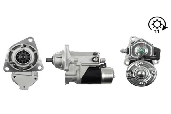
Commercial vehicle electrical equipment lives in a genuinely hostile thermal environment: a starter bolted close to the exhaust manifold, an alternator under a bonnet that soaks at 90 °C after shutdown, both expected to work on a cold morning and a hot afternoon alike. Heat soak after the engine stops is often the real design case, because there is no airflow and no coolant movement at all. Our commercial vehicle range is built around that reality rather than around a laboratory duty cycle.
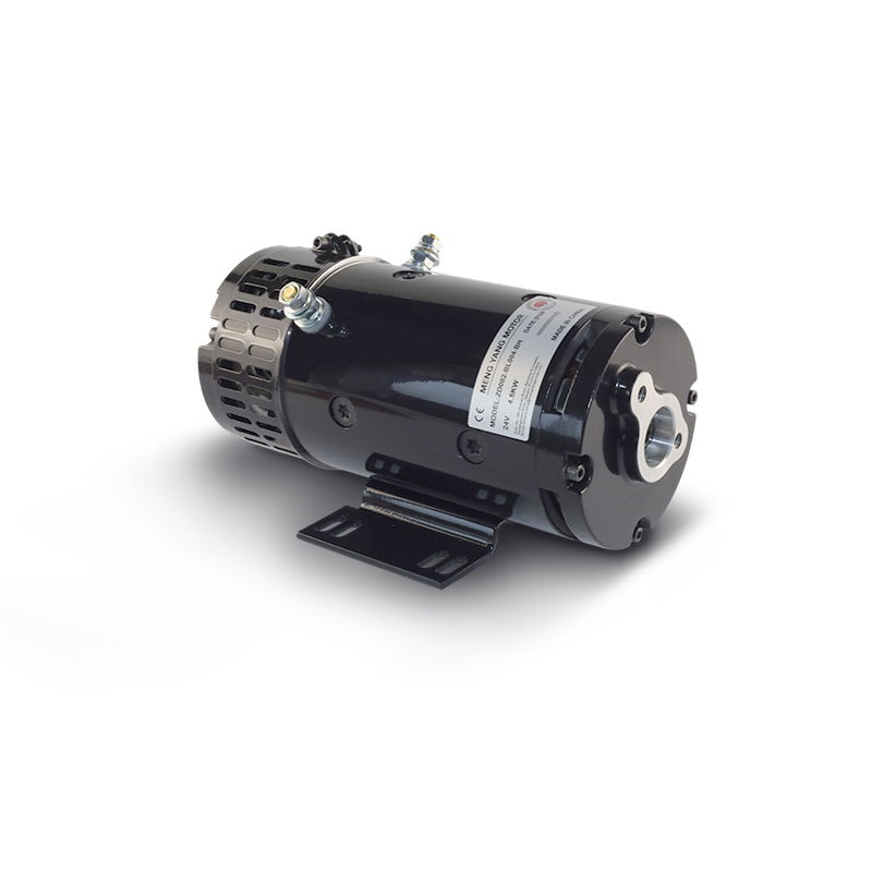 Storage Truck Low-Voltage Drive MotorLow-voltage motor for battery-powered material handling, with torque up to 11 N·m and quiet 55 dBA operation for frequent start-stop warehouse duty.View Product →
Warehouse and logistics equipment brings a different pattern: frequent starts, long periods of low-speed high-torque work, and enclosures where airflow is limited by the truck itself. Here the thermal answer is usually a generously sized frame combined with a cooling path that does not depend on shaft speed.
 CBBD Hydraulic Power-Pack AC MotorCompact AC motor for hydraulic power packs, available in 550–3000 W two- and four-pole versions for short repetitive duty in tight installations.View Product →
Tank-mounted hydraulic power units are another familiar case. The motor sits in a tight compartment, often with the oil reservoir acting as an unintended heat source, and the duty cycle is short but repetitive. Selecting for the RMS duty rather than the peak helps more than any cooling add-on.
Modeling, Testing, and Verification
We rarely rely on a single calculation. A lumped-parameter thermal network gives a fast estimate of winding, core, and frame temperatures; electromagnetic finite-element analysis supplies the loss map that feeds it; and CFD is reserved for cooling circuits where the airflow itself is uncertain. None of these replaces a heat run on the dynamometer, where the machine is held at its worst-case duty point until temperatures stabilise and the thermal time constant is recorded. Thermocouples on the end windings, resistance-based average temperature, and an infrared survey together give a picture that a single sensor never can.
Field Practices That Keep a Motor Alive
- Clean the fins and fan cover on a schedule; a mat of dust is an insulation blanket in reverse.
- Verify the real ambient temperature, especially at the top of a enclosure where hot air collects.
- When an inverter is fitted, check whether the motor still has adequate cooling below half speed.
- Set overload protection for the actual insulation class, not the nameplate current alone.
- Track insulation resistance and winding resistance over time; a slow upward drift in resistance is an early thermal warning.
- Watch bearing temperature separately — it often rises before the winding shows anything.
Thermal management is rarely a single clever feature. It is a series of sensible choices: honest loss accounting, a cooling path matched to the real duty cycle, insulation margin that respects the difference between average and hotspot temperature, and a manufacturing process that does not quietly undo the design. That is the approach we have taken at Jiangsu Mengyang Motor Manufacture since 1997, working with customers across industrial automation, construction machinery, intelligent logistics, and commercial vehicles to match the machine to the heat it will actually face.
If you are working through a thermal problem — an overheating replacement motor, a new duty cycle, or a compact installation with no room for a bigger frame — our engineering team is glad to look at it with you. Get in touch and share the operating conditions; a short conversation usually saves a long trial.