 English
 中文简体
中文简体 русский
 Français
 Español
 عربى
عربىA dump trailer that lifts an empty bed without complaint, then stalls halfway up under a full load, is usually not reporting a pump failure. Far more often, the DC motor driving that pump was selected on headline kilowatts alone, while the figures that actually decide the outcome—torque at peak system pressure and an honest duty-cycle rating—went unchecked.
Hydraulic DC motor applications succeed or fail on three things: starting torque matched to the pump's pressure demand, a duty rating that reflects the real working cycle, and thermal margin inside the compartment the motor actually occupies. Get those three right and the rest of the specification falls into place. This article sorts out what the term covers, how the motor-pump pairing is sized, and what a buyer should verify before signing a purchase order.
One Term, Two Different Machines
In purchasing conversations, a hydraulic DC motor almost always means a DC electric machine built to spin a hydraulic pump—the power core of a mobile power pack that also carries a small reservoir, a gear pump, and a valve block. A hydraulic motor is a different device entirely: a gear, gerotor, vane, or piston unit that converts pressurized fluid back into rotation at the point of work. The two often share the same machine, with the DC motor pressurizing fluid upstream and the hydraulic motor doing mechanical work at a wheel, winch, or auger.
The confusion is forgivable because the two domains map onto each other cleanly. Pressure behaves like voltage, flow like current, and torque-speed behavior translates so reliably that a series-connected DC motor and a pressure-compensated hydraulic motor share almost identical torque-speed characteristics. Engineers who come from fluid power can therefore often read a DC motor curve correctly right away. For the underlying fundamentals—excitation types, speed behavior, construction—the guide to DC motor working principles and types is a solid next step.
Sizing the Motor to the Pump: Torque, Speed, and Duty
Many mobile power packs couple the pump directly onto the motor's extended splined shaft—no belt, no gearbox, and no ratio to hide behind. The motor sees the pump's full pressure torque at whatever speed battery voltage supports, typically 2,500 to 3,400 rpm on 12 V and 24 V systems.
The sizing arithmetic fits in one line: pump shaft torque in newton-metres is approximately pressure times displacement, divided by 2π and again by mechanical efficiency. A 2.1 cc/rev gear pump working at 210 bar with 85% efficiency therefore needs roughly 8 Nm, and at 3,000 rpm that is about 2.5 kW of mechanical output—enough to draw 230 A or more from a 12 V bus once wiring and contactor losses join in. Two consequences follow:
- Cable gauge, solenoid rating, and battery condition belong to the motor specification. Half a volt lost in the harness reduces breakaway torque at precisely the moment it matters.
- Duty cycle is a primary rating, not a footnote. Tipper and tail-lift motors run S2 short-time duty—a 45-to-90-second lift followed by a long cooldown—or S3 intermittent duty with a defined repetition rate. Oversizing to S1 "for safety" adds cost and weight without adding value; undersizing the duty rating cooks windings within months.
Excitation choice completes the picture. Permanent-magnet frames in the 78-79 mm diameter class deliver compact, efficient output at moderate pressures, while wound-field series frames at 114-127 mm produce the very high starting torque that high-pressure packs demand. Segmenting a product range by frame diameter and excitation, as experienced DC motor manufacturers do, exists precisely so buyers can move between these two curve shapes without changing suppliers.
The Specification Points That Decide Performance
When quotations land side by side, the gap between an acceptable motor and a marginal one sits in a handful of line items. The table below gathers the checkpoints that decide whether a hydraulic DC motor survives its application—each should be verified against the measured duty cycle rather than the catalog cycle.
| Parameter | Typical Range in Hydraulic Duty | Why It Decides Performance |
|---|---|---|
| Rated voltage | 12 V or 24 V DC (mobile); 180-220 V DC (fixed DC-bus installations) | Sets current draw; a 12 V motor delivering 2.5 kW pulls well over 200 A at the pressure spike |
| Output power | Approximately 0.8-5.5 kW for mobile power packs | Determines the achievable pressure-and-flow product at the pump |
| Starting torque | Series-wound designs: roughly 3-5 times rated torque | Breaks pump stiction and builds pressure from zero speed |
| Duty rating | S2 short-time (commonly 2-10 min) or S3 intermittent | A mismatched duty rating is a common root cause of overheated windings |
| Insulation class | Class F or H | Manifold heat and cramped compartments leave little thermal margin |
| Protection rating | IP54 to IP67 depending on mounting | Road spray, dust, and washdown reach motor vents quickly |
One item rarely printed on datasheets deserves explicit attention: connection construction. At currents above 200 A, a soldered joint that would serve a household appliance indefinitely can soften and fail in a hot power-pack compartment; brazed armature connections are the accepted answer at these currents, and confirming them costs one question during a supplier audit.
Brushed or Brushless: Matching Commutation to the Cycle
Why brushed designs still dominate mobile power packs
For a power pack that runs a dozen short cycles a day, a brushed machine remains the rational default. Series-wound brushed DC motors deliver their highest torque at stall, tolerate rough battery voltage, need no controller in a wet and dirty compartment, and cost a fraction of an equivalent brushless system. Brush life—the usual objection—stops mattering at these duty levels, because a motor running minutes per day measures brush life in years. Permanent-magnet brushed frames trade some starting torque for compactness and efficiency, which suits medium-pressure packs on tail lifts and small tippers.
brushed DC motor platforms built for mobile hydraulic duty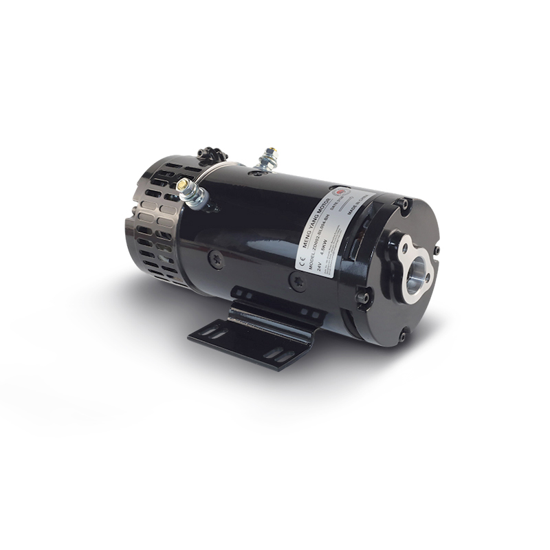 Brushed DC Motors for Hydraulic Power PacksSeries-wound and permanent-magnet brushed frames deliver strong stall torque without a controller, a rational default for packs running short daily cycles on tail lifts and small tippers.View Product →
Where brushless earns its premium
Brushless designs change the economics once duty becomes long, frequent, or fully sealed. With no brush gear to wear and efficiency a few points higher, a BLDC motor rejects less heat into the enclosure—a real advantage inside closed hydraulic cabinets and washdown environments. Electronic commutation also gives precise speed control, which electro-hydraulic actuators and positioning functions put to work. The trade-off is a controller that becomes the reliability-critical component, so in crude mobile environments the brushed machine frequently still wins on total installed risk.
brushless DC motors for sealed and high-cycle applications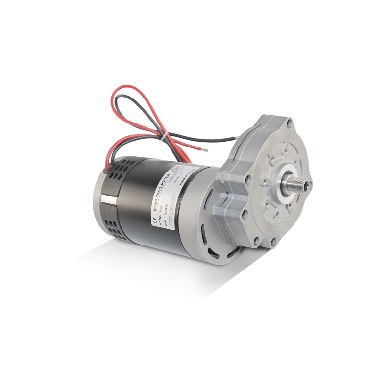 Brushless DC Motors for Sealed DutyWith no brushes to wear, higher efficiency, and precise electronic speed control, BLDC motors suit long, frequent, or fully enclosed duty where heat rejection and control matter.View Product →
Where These Motors Earn Their Keep
The same matching logic repeats across a short list of equipment families, each sitting on a known side of the mobile-versus-stationary divide.
Mobile packs feed from vehicle batteries: dump and tipper bodies lifting rated loads in under two minutes, tail lifts and dock levellers that must break away cold on a winter morning, and the pump motors of counterbalance and warehouse trucks that see hundreds of short cycles per shift. That last group sits where hydraulics meets high-cycle electric drive, and projects involving intelligent logistics equipment tend to scrutinize duty ratings closely.
Stationary packs fed from the grid play by different rules: longer duty, better cooling, and usually a three-phase machine in place of DC. A hydraulic power pack motor designed for continuous industrial cycles often shares mounting and shaft dimensions with its mobile cousin, letting equipment builders standardize manifolds across both power sources. Add electro-hydraulic actuators, steering units, and workshop lifts to the list, and the pattern is clear—wherever a pump needs a burst of torque from a confined space, this pairing shows up.
hydraulic power pack motors for stationary, grid-fed systems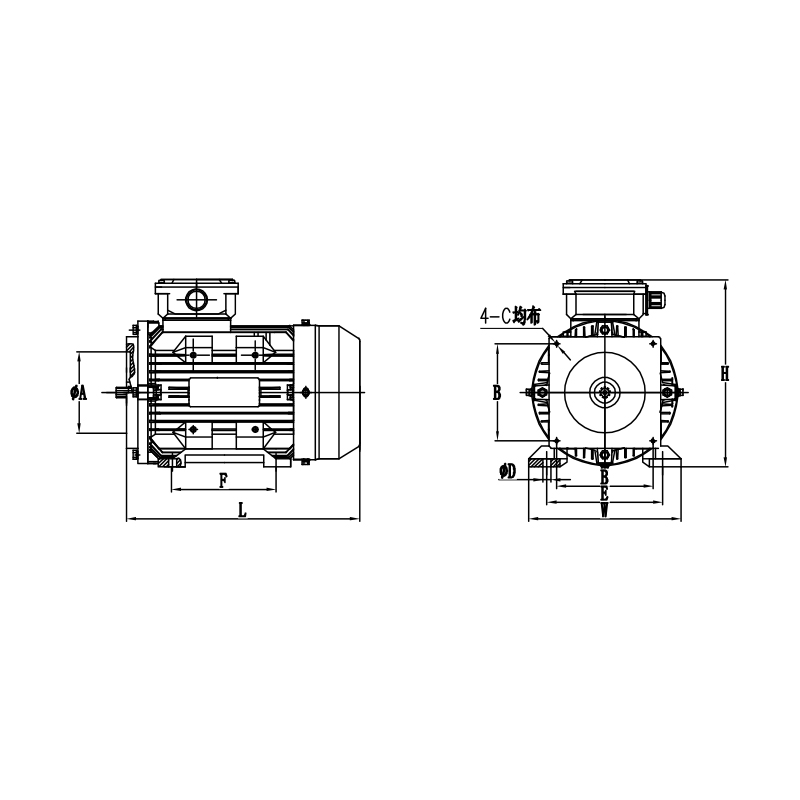 CBBD Hydraulic Power-Pack MotorA stationary-pack motor with up to 83% efficiency, 2- or 4-pole options, and a 113 x 113 mm flange, offering mounting flexibility and surge resistance for hydraulic pump drives.View Product →
What to Verify Before Committing to a Supplier
Hydraulic DC motors are forgiving in samples and unforgiving in batches, so disciplined buyers check four things before committing:
- Dynamometer data at the real duty point: torque at rated pressure and at working temperature, not a single rated figure quoted at room temperature.
- Commutation and connection construction: brush grade, spring pressure, and whether high-current joints are brazed rather than soldered.
- Thermal protection options: winding thermal switches or fuses that protect a mis-applied duty cycle from destroying the motor.
- Component-level support: armatures, brush holders, and field frames available as replacement parts, because in service fleets the armature is the predictable wear item and its availability decides repair turnaround.
A supplier that designs and winds its own armatures—rather than only assembling motors—can also answer the questions behind the questions: why a particular slot fill was chosen, what commutator finish tolerance is held, and how sample units trace back to production tooling. Those answers say more about batch-to-batch consistency than any datasheet line.
Match the motor to the pump's pressure demand, take the duty cycle seriously, and choose commutation by cycle length and environment—that covers the core discipline in three sentences. The hydraulic-electric analogy makes the initial step intuitive; only measured, duty-point validation makes the second and third safe. Buyers who insist on that validation early, while pump and motor can still be paired as one system, avoid many of the failures that otherwise surface in the field.