 English
 中文简体
中文简体 русский
 Français
 Español
 عربى
عربىWhat an AC Drive Motor Is
An AC drive motor is an electric motor that runs on alternating current and is paired with a variable frequency drive, a control unit that adjusts the voltage and frequency supplied to the motor so its speed and torque can be changed while it is running. Instead of spinning at one fixed speed tied directly to the power line frequency, the motor responds to a control signal that raises or lowers rotational speed to match whatever a machine or process actually needs at a given moment. This pairing of motor and drive is what separates an AC drive motor from a conventional fixed-speed AC motor connected straight to mains power.
The practical value of this setup shows up in energy use and mechanical control. A pump or fan that only needs to run at partial capacity for part of a shift can be slowed down rather than throttled with a valve or damper, which cuts electrical consumption and reduces mechanical stress on connected equipment. Because torque and acceleration can be shaped electronically, the same motor can also start loads gently, avoiding the current spikes and mechanical shock that come with direct-on-line starting.
How Variable Frequency Control Works
The drive converts incoming AC power to DC and then reconstructs it into a new AC waveform at a frequency chosen by the control settings, a process commonly called pulse width modulation. Since the synchronous speed of an AC motor is proportional to the frequency of the supply, changing that frequency changes the motor's rotational speed. A motor rated for 60Hz operation, for example, turns roughly half as fast when the drive supplies it with 30Hz, and the relationship holds across a wide portion of the usable frequency range.
Voltage is adjusted alongside frequency to keep the magnetic flux inside the motor within a workable range, a technique often referred to as volts-per-hertz control. Departing from that ratio at low speeds can cause the motor to overheat or lose torque, so drives include compensation logic to maintain adequate magnetization even when the motor is running well below its rated speed. More advanced drives use vector control or sensorless flux estimation to hold torque steady even under changing loads, which matters in applications like conveyors that start under a full load or hoists that need precise positioning.
Core Components and Materials
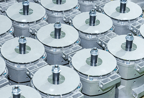
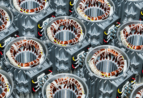
Inside the motor housing, a stationary stator wound with copper coils generates a rotating magnetic field, while a rotor—typically a squirrel-cage design made of laminated silicon steel with embedded aluminum or copper bars—turns in response to that field. The laminations reduce eddy current losses, which keeps the motor cooler and improves efficiency over solid iron cores. Bearings support the rotor shaft and are selected based on load direction and speed; sealed ball bearings are common in general industrial motors, while larger units may use roller bearings rated for heavier radial loads.
Winding insulation is graded by the temperature it can tolerate before breaking down, and this rating determines how much thermal margin a motor has during continuous operation. The table below summarizes commonly used insulation classes and their associated temperature limits.
| Insulation Class | Maximum Temperature | Typical Use |
|---|---|---|
| Class B | 130°C | General industrial motors |
| Class F | 155°C | Motors under variable or elevated loads |
| Class H | 180°C | Motors in demanding thermal environments |
Motor Types Used With AC Drives
Induction motors are commonly paired with variable frequency drives because of their simple construction and tolerance for a wide speed range. Permanent magnet synchronous motors are used where higher efficiency at partial load or a smaller physical footprint is needed, since the rotor's magnetic field does not depend on induced current. A less common but increasingly relevant category is the submerged, or oil-immersed, motor, where the rotor and stator sit inside a bath of hydraulic fluid rather than open air, changing how heat and lubrication are managed inside the unit.
- Squirrel-cage induction motors, used across pumps, fans, and conveyor drives
- Permanent magnet synchronous motors, used where compact size and steady torque at low speed matter
- Wound-rotor motors, used in applications needing adjustable starting torque
- Oil-immersed submerged motors, used in compact hydraulic power units
Oil-Immersed Motor Design in Hydraulic Power Units
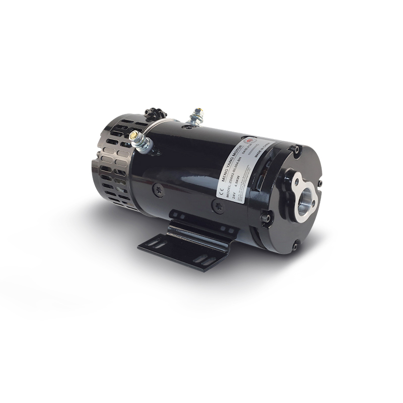
One notable variation on the standard air-cooled AC drive motor is a submerged design, where both the rotor and stator operate fully immersed in hydraulic fluid rather than exposed to open air. Because hydraulic fluid conducts heat away from the windings far more effectively than air, this design avoids the thermal bottlenecks that limit continuous-duty performance in traditional air-cooled units. Motors built this way commonly operate in a power range spanning roughly 550W to 3000W and can sustain extended operation without the thermal buildup that would otherwise force a reduction in duty cycle.
The fluid bath also provides continuous lubrication to internal bearings, which lowers friction and wear compared to grease-lubricated designs, and it removes the need for shaft seals that would otherwise wear against a rotating surface. The combined effect is noticeably quieter operation, which makes this motor type suitable for laboratory settings or indoor installations where noise levels need to stay low. To hold up against constant fluid contact, the internal wiring uses oil- and heat-resistant conductor material with insulation typically rated Class B or Class F, protecting the electrical system from gradual corrosion. Physical size for these units generally falls between 158mm and 235mm, and the housing itself often carries an open IP00 rating, relying on the surrounding hydraulic reservoir to provide the secondary environmental protection that a sealed enclosure would normally supply. This construction is used in general-purpose hydraulic power packs, where the motor drives a hydraulic pump directly and benefits from the fluid's dual role as both coolant and lubricant.
Where AC Drive Motors Are Applied
Variable speed AC drive motors show up wherever a process benefits from adjustable flow, pressure, or motion rather than a single fixed output. In water treatment plants, pumps driven by these motors adjust flow rate to match demand through the day instead of running continuously at full output. In HVAC systems, fan motors slow down during periods of lower cooling demand, which reduces both energy draw and duct noise. Machine tools use drive-controlled spindle motors to vary cutting speed depending on material and tool geometry, while packaging lines use them to synchronize conveyor speed with upstream and downstream equipment.
Hydraulic power units built around compact submerged motors are used in equipment such as lifting platforms, injection molding auxiliary systems, and mobile hydraulic tools, where a self-contained, low-noise power source is preferable to a separately cooled motor and pump assembly. General machinery applications across the manufacturing sector also rely on AC drive motors to run compressors, mixers, and material handling equipment, adjusting speed as batch sizes or process steps change.
Maintenance Considerations
Routine maintenance for AC drive motors centers on monitoring winding temperature, checking insulation resistance periodically, and keeping cooling paths clear of dust or debris in air-cooled designs. Bearing lubrication intervals depend on duty cycle and ambient temperature, and vibration analysis can catch bearing wear before it leads to a failure. For submerged motor units, fluid condition matters as much as electrical checks; the hydraulic oil should be inspected for contamination and topped up or changed according to the equipment manufacturer's schedule, since degraded fluid affects both cooling performance and lubrication quality.
Signals Worth Tracking During Operation
Unusual noise, a rise in operating temperature beyond the motor's rated range, or a change in current draw at a given load are all signs worth investigating before they develop into a larger issue. Drive parameters such as output frequency and torque limits are typically logged automatically, giving maintenance staff a record to compare against baseline readings taken when the equipment was initially commissioned.