 English
 中文简体
中文简体 русский
 Français
 Español
 عربى
عربىBrushed DC Motor Engineering Guide: Component Design, Materials, and Application Matching
Selecting the right brushed DC motor for a production line, an appliance platform, or a mobile equipment design is rarely just a matter of matching voltage and power. Torque curve shape, brush material chemistry, commutator geometry, insulation class, and duty cycle all interact to determine whether a motor survives 500 hours or 5,000 hours in the field. This guide moves past the basic definition of brushed DC motor technology and focuses on the engineering decisions that separate a motor that merely runs from one that performs reliably across its full rated life.
Anatomy of a Brushed DC Motor: Component-Level Breakdown
Every brushed DC electric motor is built from a small number of subsystems, but the tolerances, materials, and assembly quality of each one determine the final performance envelope. Below is a breakdown of the core components found in a typical brush motor DC platform.
Generates the fixed magnetic field the armature rotates within. Permanent magnet designs use ferrite or rare-earth (NdFeB) segments bonded or sleeved into the housing; wound-field designs use copper field coils instead, allowing adjustable field strength for specialized torque-speed profiles.
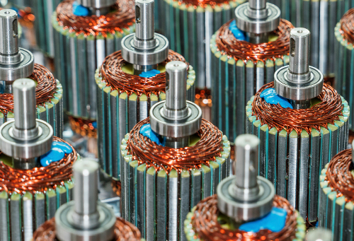
A laminated steel core wound with multiple coil sets, each terminated to a commutator segment. Lamination thickness and stacking quality directly affect eddy current losses and therefore overall motor efficiency.
A segmented copper ring mounted on the rotor shaft. As it rotates past the stationary brushes, it reverses current direction in each armature coil at the correct rotational position, which is the mechanical process at the heart of how does a brushed DC motor work.
Spring-loaded conductive blocks that maintain continuous sliding contact with the commutator. Brush geometry, spring force, and contact area are tuned to balance electrical conductivity against mechanical wear rate.
Positions each brush at the correct neutral plane angle and applies consistent spring pressure. Incorrect spring tension is one of the leading causes of premature brush wear and unstable commutation.
Precision bearings absorb radial and axial loads while maintaining rotor-to-stator air gap tolerance. Housing material and end-cap sealing determine the motor's resistance to dust, moisture, and vibration in the target application.
Brush Material Engineering: Selecting the Right Contact Element
Because DC motor brushes are the primary wear component in any brushed DC motor, material selection is one of the highest-leverage engineering decisions in the design. Different carbon and metal-graphite compositions trade off current-carrying capacity against mechanical wear and commutation smoothness.
| Brush Material | Current Density Range | Typical Application | Wear Characteristic | Operating Temperature |
| Carbon | Low to moderate | Low-speed, light-load appliance motors | Slow, self-polishing wear | Up to 80°C |
| Electro-graphite | Moderate | General-purpose industrial brush motor DC units | Stable wear, low commutator scoring | Up to 150°C |
| Metal-graphite (copper-graphite) | High | Automotive actuators, high-current starter motors | Higher conductivity, moderate wear | Up to 120°C |
| Resin-bonded graphite | Moderate to high | High-speed precision instrumentation motors | Low noise, fine commutator finish retained | Up to 180°C |
Brushed DC Motor Configurations by Winding Type
Not every brushed DC motor produces the same torque-speed relationship. The winding configuration determines whether a design is suited to constant-speed applications or to high-starting-torque duty cycles.
Fixed field strength from permanent magnets gives a linear torque-speed curve, simple two-wire control, and compact size. This is the most widely produced brushed DC motor type for consumer and light industrial equipment.
Field and armature windings are connected in series, producing very high starting torque at low speed. Speed varies significantly with load, making this configuration well suited to starter motors and traction applications.
Field winding is connected in parallel with the armature, delivering more stable speed regulation across varying loads compared to series-wound designs, at the cost of lower starting torque.
Combines series and shunt windings to balance strong starting torque with reasonable speed stability, used where load conditions fluctuate but speed control still matters.
Understanding the Torque-Speed Curve
Every brushed DC motor has a characteristic torque-speed curve that describes how output torque changes as rotational speed increases under a fixed applied voltage. At zero speed (stall condition), torque is at its maximum because current draw through the armature is highest and unopposed by back-EMF. As the rotor accelerates, back-EMF rises and opposes the applied voltage, reducing net current and therefore torque, until the motor reaches its no-load speed where torque output approaches zero. Engineers use this curve to select the correct operating point for a given mechanical load, since running a motor far from its rated torque point for extended periods accelerates brush and commutator wear and reduces efficiency. PMDC motors typically show a near-linear torque-speed relationship, which makes them easier to predict and control than series-wound configurations, whose curve is markedly non-linear and more load-dependent.
Typical Performance Parameters
While exact figures vary by frame size and application, the table below outlines the parameter ranges commonly specified when sourcing a brushed DC electric motor for industrial or OEM integration.
| Parameter | Typical Range |
| Rated Voltage | 6V – 220V DC |
| Power Output | 1W – 5kW |
| Rated Speed | 1,000 – 6,000 RPM |
| Starting Torque | 150% – 400% of rated torque |
| Efficiency | 65% – 85% |
| Insulation Class | Class B / F / H |
| Ingress Protection | IP20 – IP55 |
| Ambient Operating Range | -20°C to 55°C |
| Brush Life (typical carbon) | 1,000 – 3,000 hours |
| Brush Life (metal-graphite, high-current duty) | 500 – 1,500 hours |
Frame Size and Enclosure Selection
Beyond electrical parameters, the physical frame and enclosure rating of a brushed DC motor determine whether it will survive the mechanical and environmental conditions of its installation. Motor frame size follows standardized diameter and mounting-flange conventions, allowing a design engineer to swap between comparable output ratings without redesigning the mechanical interface. Enclosure selection is equally important: open frame designs allow maximum airflow across the windings for continuous-duty cooling, while totally enclosed designs sacrifice some thermal headroom in exchange for protection against dust, splashing liquids, or washdown environments common in food processing and outdoor equipment.
Best airflow and heat dissipation, suited to clean indoor environments such as light assembly equipment and instrumentation.
Sealed housing without an external fan, relying on surface radiation for cooling; suited to dusty environments with moderate duty cycles.
Sealed housing with an external cooling fan, allowing higher continuous power output than TENV designs while still resisting dust ingress.
Gasketed end caps and shaft seals rated for direct water exposure, used in outdoor, marine, and sanitation-sensitive equipment.
Where Brushed DC Motor Technology Delivers Value
Despite the growth of electronically commutated alternatives, brushed DC motor platforms remain a preferred choice across a wide range of end-use categories because of their simple control interface and strong low-speed torque.
Series-wound brush motor DC units deliver the high starting torque needed for drills, saws, and grinders under variable load conditions.
Window lifts, seat adjusters, wiper systems, and HVAC blower motors rely on compact PMDC units for cost-effective, durable actuation.
Vacuum cleaners, kitchen mixers, and personal care devices use brushed DC motor designs for their favorable torque-to-cost ratio.
Conveyor drives, pumps, and material handling equipment benefit from straightforward voltage-based speed control without added driver electronics.
Adjustable beds, mobility aids, and rehabilitation devices use brushed DC electric motor units for smooth, controllable, low-noise motion.
Smaller-frame brushed DC motor units remain common in lower-cost robotic joints and positioning systems where budget constraints outweigh the need for brushless commutation electronics.
Seed metering drives, valve actuators, and irrigation controls use sealed brush motor DC units for their tolerance of dust and vibration.
Trolling motors, winches, and deck actuators use sealed brushed DC motor housings rated for saltwater spray and continuous vibration exposure.
Choosing Between Brushed and Brushless: An Application-Fit View
The brushless DC vs brushed motor decision should be driven by application requirements rather than by cost or performance alone. The table below reframes the comparison around real-world scenarios rather than raw specifications.
| Application Scenario | Recommended Type | Reason |
| Cost-sensitive, high-volume production | Brushed DC Motor | Lower unit cost, no external driver circuit required |
| Sealed or hazardous environments | Brushless DC Motor | No brush sparking, reduced ignition risk |
| High starting torque, intermittent duty | Brushed DC Motor | Series-wound configuration excels at load-start torque |
| Continuous 24/7 operation | Brushless DC Motor | No wear component, longer maintenance-free runtime |
| Simple two-wire voltage control | Brushed DC Motor | Speed control without added electronics |
| Confined spaces requiring compact controllers | Brushed DC Motor | No dedicated commutation driver board needed |
| Precision speed regulation under variable load | Brushless DC Motor | Electronic feedback control maintains tighter speed tolerance |
Extending Brushed DC Motor Service Life: Maintenance Engineering
Diagnosing Common Brushed DC Motor Faults
Understanding the early warning signs of wear helps prevent unplanned downtime. The table below lists common symptoms observed in brushed DC motor operation along with their most frequent root causes.
| Symptom | Likely Cause | Recommended Action |
| Excessive sparking at brushes | Worn brushes, incorrect spring tension, or commutator surface damage | Inspect and replace brushes, verify spring force, resurface commutator if scored |
| Intermittent operation | Brush contact loss due to vibration or worn brush length | Check brush length against minimum spec, verify holder alignment |
| Reduced torque output | Weakened magnets, worn bearings, or brush contact resistance | Measure no-load current and compare to baseline, inspect brush contact area |
| Unusual noise or vibration | Bearing wear, rotor imbalance, or loose mounting | Check bearing play, verify rotor balance, inspect mounting hardware |
| Overheating under normal load | Blocked ventilation, degraded insulation, or undersized frame for duty cycle | Clear airflow paths, measure winding resistance, reassess frame sizing |
Manufacturing Quality Control for Brushed DC Motor Production
Consistent field performance starts on the production line. Dynamic rotor balancing minimizes vibration-induced bearing wear, dielectric withstand testing confirms winding insulation integrity, no-load current testing verifies mechanical friction is within spec, back-EMF testing confirms winding uniformity across the coil set, and extended endurance runs validate brush and commutator wear rates against the rated design life before a brushed DC motor platform is released for volume production.
Copper wire, magnet segments, and brush stock are checked against purity and dimensional specifications before entering the winding process.
Armature coils are wound to precise turn counts and varnish-impregnated to resist moisture, vibration-induced loosening, and thermal cycling.
The commutator surface is machined to a controlled roundness and finish before final assembly, directly influencing brush contact stability.
Every completed brushed DC motor unit undergoes voltage, current, speed, and torque verification against its rated nameplate values before packaging.
Custom Design Considerations for OEM Integration
Beyond selecting an off-the-shelf frame size, many equipment designs benefit from motor parameters tailored to the specific application. Shaft length, diameter, and keyway or D-flat features should match the mating component without requiring secondary machining. Wire lead length, connector type, and exit direction affect harness routing and assembly time on the customer's line. Mounting flange pattern (face mount, base mount, or servo-style flange) should align with existing bracket designs to avoid redesign costs. Where noise is a concern, skewed armature slots and precision-balanced rotors reduce audible commutation ripple. For applications with wide ambient temperature swings, insulation class and bearing grease formulation should be matched to the expected thermal range rather than left at generic defaults. Working through these details early in the design cycle prevents costly late-stage changes once a brushed DC motor platform has already been tooled for production.
Frequently Asked Technical Questions
What is a brushed DC motor best suited for?
Applications requiring high starting torque, simple voltage-based speed control, and lower upfront component cost, such as power tools, actuators, and appliance drives.
Are brushed DC motors still used in modern equipment?
Yes. Despite the rise of electronically commutated alternatives, brushed DC motor units remain standard in cost-driven, high-starting-torque, and simple-control applications.
What are the disadvantages of a brushed DC motor?
Brush wear requires periodic maintenance, sliding contact generates some electrical noise and sparking, and efficiency is generally lower than electronically commutated alternatives.
What are the advantages of brushed DC motors?
Simple two-wire control, strong starting torque, lower component cost, mature manufacturing processes, and straightforward speed adjustment via input voltage.
Do all DC motors have brushes?
No. Brushless DC motors use electronic commutation via Hall sensors and a driver circuit instead of a mechanical brush-commutator interface.
How can commutation noise from DC motor brushes be reduced?
Proper brush material selection, correct spring tension, a well-finished commutator surface, and appropriate filtering capacitors at the terminals all help reduce electrical noise during operation.
How is the correct frame size chosen for a brushed DC motor?
Frame size is selected based on required continuous torque, duty cycle, thermal environment, and available mounting space, then cross-checked against the motor's rated power curve.
What determines brush replacement intervals?
Replacement intervals depend on brush material, current density, duty cycle, ambient temperature, and contamination exposure, and are typically established through endurance testing at the design stage.