 English
 中文简体
 русский
 Français
 Español
 عربى
If you have ever opened up a starter motor or an industrial induction motor, you have probably held a lamination stack without realizing it. It looks like a solid block of steel and feels like one, yet it is actually dozens or hundreds of thin sheets pressed so tightly together that the joints almost disappear.
We have been manufacturing motors and motor components since 1997, and lamination stacks come up in almost every technical conversation we have with engineers and buyers. The same questions tend to repeat: why not machine a core from one piece of steel, does 0.35 mm really beat 0.5 mm, and how do you choose between a bonded stack and a welded one? Here is what we have learned on the shop floor.
What Exactly Is a Lamination Stack?
A lamination stack is a magnetic core built from many thin sheets of electrical steel. The individual sheets are the laminations; once they are stacked, compressed and locked together, they form the stack.
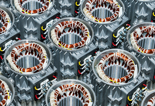
Each sheet is punched, laser-cut or fine-blanked into the profile the magnetic circuit needs: a stator ring with slots for windings, a rotor with slot openings and a shaft bore, or an armature core that will later carry a commutator. Between neighbouring sheets sits a thin insulation layer, sometimes an oxide layer grown during annealing, more often a purpose-applied coating. The whole assembly is then fastened by one of several methods, which we will come to shortly.
Why not machine the core from solid steel?
Because a changing magnetic field drives circulating currents through any conductive material. In a solid steel core, those eddy currents loop freely through the bulk of the metal, heating it and wasting energy that should reach the shaft as torque. Cutting the core into thin, insulated sheets interrupts those loops and shrinks them dramatically. Thinner sheets mean smaller loops and lower losses, right up to the point where handling, stacking and material cost stop making sense.
This is the reason a lamination stack exists at all. Every other decision around it, from joining method to coating type to burr height, matters only because it either protects or undermines that single job.
Thickness, Steel Grade and Coating: Three Choices That Decide Performance
Thickness
For 50 Hz and 60 Hz machines, 0.5 mm and 0.35 mm are the everyday choices. Core loss climbs roughly with the square of frequency, so as speed rises, thinner material starts to pay for itself: 0.2 mm and 0.1 mm grades appear in high-speed and inverter-fed designs. A general-purpose industrial motor rarely needs 0.1 mm steel; a high-speed spindle often does.
Steel grade
Electrical steels are specified by guaranteed core loss at a defined flux density and frequency, together with thickness and silicon content. Lower-loss grades run cooler but are harder and more brittle, which shortens stamping die life and makes burr control harder. A grade that looks perfect on a data sheet can create real production problems.
Insulation coating
Coatings are grouped by temperature class and by how well they tolerate punching and welding. Organic coatings punch cleanly but burn away under a weld; inorganic and ceramic-filled coatings survive higher temperatures but are tougher on dies. Choose a coating that fights your joining process and you will spend months chasing weld porosity and short circuits between sheets.
How a Lamination Stack Is Assembled
Once the sheets are cut, coated and stacked to height, they have to become one rigid body that survives handling, winding, dipping and years of vibration. Five methods cover most of what crosses our desks.
| Method | How it works | Where it fits | What to watch |
|---|---|---|---|
| Interlocking | Dimples or dovetail tabs pressed into each sheet lock into the sheet below during stacking | High-volume stator and rotor cores for small and medium motors | Local short circuits between sheets slightly raise core loss; dies need regular maintenance |
| Welding | Four to eight laser or TIG welds run along the outer diameter | Larger stator frames that need high rigidity | Weld heat damages nearby coating and can distort the bore |
| Riveting or cleating | Through-rivets or metal cleats clamp the stack | Small cores and low-volume builds | Adds material and can loosen after repeated thermal cycling |
| Adhesive bonding | Sheets pre-coated with heat-activated adhesive are stacked and cured under pressure | Efficiency-focused, low-noise and thin-gauge designs | Higher material cost and a tightly controlled curing cycle |
| Clamping or bolting | End plates and through-bolts hold the stack in compression | Prototypes, repairs and very large cores | Simple and reworkable, but bulky and less rigid |
None of these methods is right in every case. Bonded stacks often run quieter and cooler because there is no interlocking short circuit and no weld heat disturbing the coating, but they add material cost and a curing step. Welding is fast and robust for thicker stacks, and it is usually the pragmatic answer for large stator frames. Core geometry, annual volume and the noise target make the decision, not preference.
Two details deserve attention whatever the method. First, burr height: if punching leaves a raised edge that pierces the coating, sheets short to each other and loss climbs. Second, stress relief annealing, which restores magnetic properties after punching and also builds up the oxide insulation many stacks rely on.
Rotor stacks bring their own considerations. Squirrel cage rotors are usually die-cast around the laminated core, permanent magnet rotors are assembled with magnets fixed into the lamination pockets, and both then have to be fitted to a shaft with the right interference and the right amount of skew to keep cogging and vibration under control.
Lamination Stacks in the Motors We Build
We manufacture our own stator and rotor cores for the AC, DC and brushless motor ranges we build, and we also supply core components to customers who assemble machines themselves. Stator cores are stacked in welded or interlocked form depending on frame size and volume, wound in house, then varnished and tested before assembly.
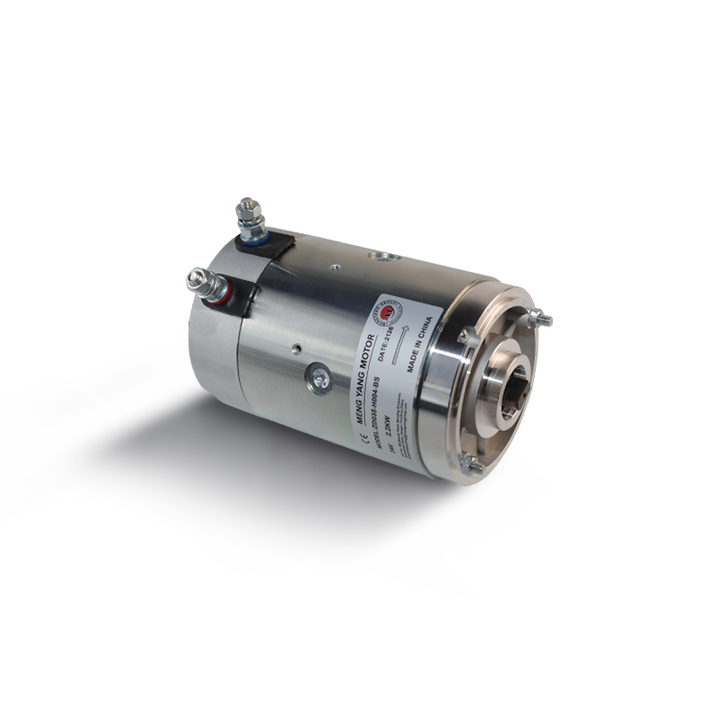
Armature cores for our DC motors and starter motors follow a slightly different route. The stack is pressed onto the shaft, commutator risers are brazed, windings are inserted, and the rotor is balanced before it reaches the line. Brazing is one of those small details that separates a starter that lasts from one that comes back: a cold joint shows up as a hot spot long before it shows up as a failure.
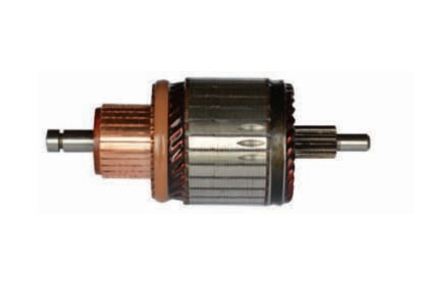 OEM/ODM Motor Armatures for Starter ComponentsBrowse starter motor armatures in Bosch universal and Chrysler Valeo-type series, with model dimensions, voltages, and service reference numbers for sourcing and design review.View Product →
Because we sit between the steel and the finished machine, we see both sides of the problem. A drawing that looks straightforward in CAD can be difficult to stack if the slot geometry leaves thin sections that deform under pressure. Working from a 70,000 square metre plant with more than 300 people across engineering, manufacturing and quality, we would rather flag that early than discover it at the tooling stage. You can read more about how we work on our company page.
What to Check Before You Source Lamination Stacks
Whether the stack ends up in a commercial vehicle starter, a warehouse truck drive motor or a general industrial pump, the checks are largely the same.
- Steel grade and the guaranteed core loss figure, not just the thickness.
- Coating type, and whether it survives your joining process.
- Stacking factor: how much of the stack height is actually steel.
- Burr height, and whether the supplier anneals after punching.
- Slot geometry, bore diameter, outside diameter and perpendicularity tolerances.
- Joining method, skew and the mechanical rigidity your application demands.
- Sample validation: core loss measurement, fit check and a short running test before tooling is committed.
Ask for these in writing. Suppliers who can answer them quickly tend to be the ones who actually control their process rather than sorting good parts from bad.
Common Questions, Short Answers
Can a bonded stack replace a welded stack?
Often yes, especially with thin gauge steel or when noise is a priority, because bonding removes the interlocking short circuits and the local weld heat. But bonding needs tooling, a controlled press-and-cure cycle and more expensive pre-coated steel. For a thick stack in a modest volume, welding usually wins on cost and simplicity.
How much does stack height matter?
More than most drawings suggest. Stack length is part of the magnetic circuit, so it affects flux, torque and how much heat the core has to shed. Height also has to be held tightly: a loose stack rattles, an over-compressed one distorts, and both show up later as noise or uneven performance.
Do thinner laminations always mean better efficiency?
Not automatically. Thinner sheets reduce eddy current loss, but they also reduce the stacking factor, increase handling cost and demand better dies. The right thickness is the one that matches your frequency, your duty cycle and your budget, and that balance is worth discussing with whoever builds the core.
If you are working through a lamination stack decision right now, whether that means a new stator profile, a thinner gauge for a high-speed design or a switch from welding to bonding, talk to us early. Send the drawing, tell us the volume and the working environment, and we can suggest a stack construction that fits, then build samples so you can measure core loss and noise before committing to tooling. That is usually cheaper than fixing a stack after the first thousand pieces.