 English
 中文简体
 русский
 Français
 Español
 عربى
A rotor is the part that does the actual turning — the piece of steel, copper and magnetism that converts electrical energy into motion, or motion back into current. Because so much depends on it, rotor manufacturing is rarely a single operation. It is a chain: stamping, stacking, shafting, conductor forming, machining, balancing, and testing, each step narrow enough that a small drift in one place shows up as noise, heat or vibration somewhere else.
We have been building motors and motor components in Jiangsu since 1997, and today our plant near Wuxi produces armatures, rotors, starters and alternators for industrial and vehicle applications. This article is what we would tell a new engineer or a new buyer walking onto our floor for the first time: what the process actually looks like, where it gets difficult, and what to ask before you place an order.
What a Rotor Has to Get Right
Strip away the drawings and a rotor has three jobs at once. It has to carry the magnetic circuit efficiently, it has to carry current safely, and it has to hold its shape at speed while getting hot. Every manufacturing decision traces back to one of those three.
In practice, most rotor problems surface as one of four symptoms: vibration, temperature rise, insulation breakdown, or electrical resistance drifting out of tolerance. Good rotor manufacturing is mostly the discipline of keeping those four out of the finished part.
The Rotor Manufacturing Process, Step by Step
The sequence below is the one we follow for laminated rotors. Specific designs add or drop steps, but the logic stays the same.
- Lamination stamping. Electrical steel strip is punched or stamped into thin sheets, with burr height and edge quality controlled because every lamination edge becomes part of the magnetic circuit.
- Core stacking and press-fitting. Laminations are aligned, then locked together by interlocking, welding, riveting or a fixture, with stack height and skew angle held to the drawing.
- Shaft insertion. The shaft goes in by press fit or shrink fit, and shaft runout is checked right after assembly rather than at the end of the line.
- Conductor forming. Depending on the design, this means aluminium die casting for a squirrel cage, copper bar insertion, wound coils, or magnets bonded and retained into the lamination pockets.
- Machining and finishing. Rotor outside diameter, shaft journals, commutators and slip rings are turned or ground, and joints such as commutator risers are brazed where that is required.
- Heat treatment, coating and impregnation. Stress relief and surface protection come before balancing, not after, because they change dimensions and mass distribution.
- Balancing. Static and dynamic balancing brings residual unbalance inside the specified grade, with material removed or added at defined correction points.
- Final inspection and testing. Electrical, insulation, dimensional and vibration checks confirm the rotor before it moves to assembly or packing.
Materials and What Each One Decides
Material choice is where cost, efficiency and durability get traded against each other. The table below shows the main decisions we discuss with customers.
| Material | Where it sits in the rotor | What it mainly decides |
|---|---|---|
| Electrical steel (silicon steel) | Lamination stack | Core loss, flux density, stamping quality |
| Carbon or alloy steel | Shaft | Stiffness, runout, fatigue life at speed |
| Aluminium | Die-cast cage | Weight and cost balance, casting porosity risk |
| Copper | Cage bars, windings, commutator | Conductivity, temperature rise, brazing quality |
| Permanent magnets | Rotor pockets or surface mounting | Torque density, demagnetisation margin, retention |
| Insulation varnish and coatings | Laminations, windings, surfaces | Inter-laminar resistance, corrosion protection, life |
Rotor Types We Build — and Where They End Up
Squirrel-cage AC rotors
These sit inside our three-phase asynchronous motors, including IEC and NEMA framed units and the gear-reduction versions used on conveyors, hoists and handling equipment. The cage is the whole story here: porosity in a die casting, or a poor bar-to-end-ring joint, shows up months later as heat.
DC armatures
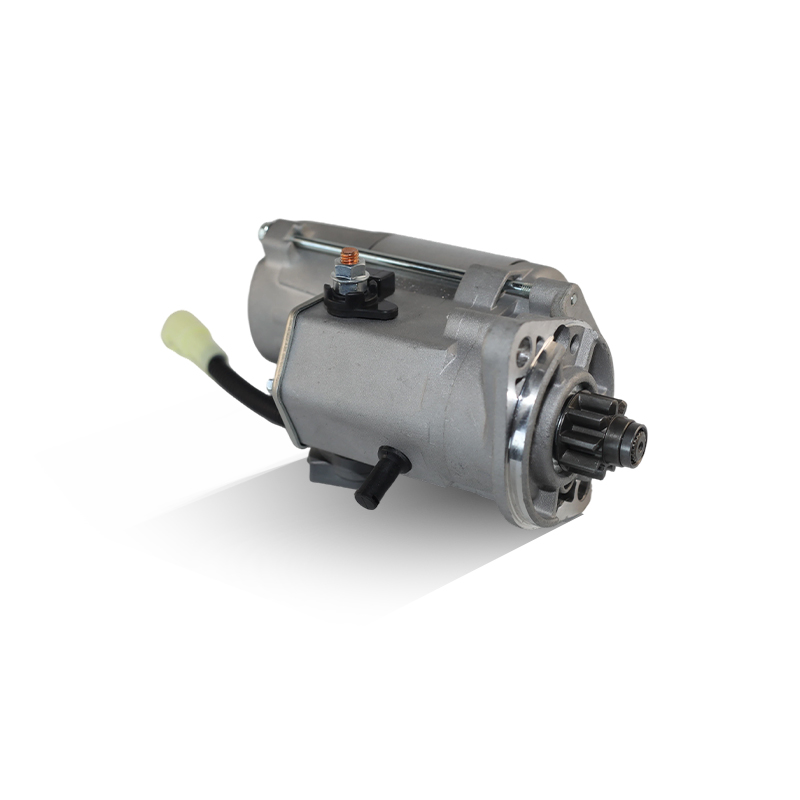
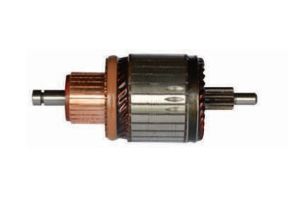
For brushed DC motors and for starter motors, the armature carries windings, a commutator and a brazed riser connection. Armatures are one of our highest-volume lines, and brazing quality is something we inspect rather than assume — a cold joint is invisible until the motor is under load.
Permanent-magnet rotors
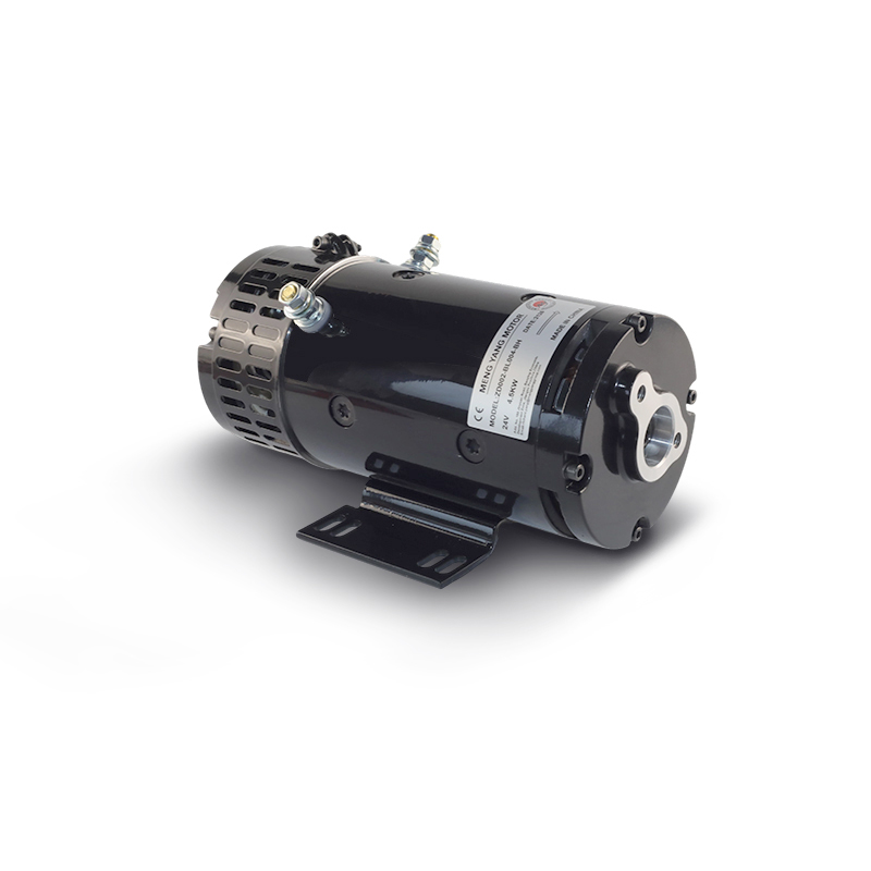
Our brushless DC range uses magnet rotors where retention and air-gap consistency matter more than raw mass. These often go into compact equipment such as sweeper brush drives, where the rotor is buried inside a housing and difficult to service.
Claw-pole and wound rotors for alternators
Alternator rotors combine a field coil, claw poles and slip rings, and they are supplied both as a sub-assembly and as a replacement component for rebuilders.
Balancing, Vibration and Tolerance Stack-Up
Balancing is the step customers ask about most, and the one most often misunderstood. A rotor can pass a balance check on a fixture and still vibrate in a motor, because vibration comes from the whole assembly: bearing fit, shaft straightness, air-gap uniformity, and how concentric the rotor is to the stator bore.
That is why we treat runout, stack skew and bearing-journal finish as rotor manufacturing variables, not as downstream problems. In our experience, catching a runout drift at the machining cell costs minutes. Catching it after the motor is assembled costs a teardown, a report and a conversation with the customer.
Quality Control: What We Check Before a Rotor Ships
- Incoming steel certificates and lamination burr measurement
- Stack height, skew angle and inter-laminar resistance
- Shaft fit, runout and journal surface finish
- Cage porosity inspection and bar-to-end-ring integrity
- Winding resistance, surge comparison and insulation resistance
- Brazed joint quality on armature risers and commutator connections
- Dynamic balance to the agreed grade, plus vibration spot checks
- Overspeed and temperature-rise verification on new designs
Where a customer needs documentation for their own quality system, we prepare inspection records alongside the shipment rather than after it.
Working With a Rotor Manufacturing Partner
If you are sourcing rotors or armatures rather than building them, a handful of questions will tell you more than a catalogue will:
- Which steps are done in-house — stamping, die casting, brazing, balancing, or only assembly?
- What balance grade and runout limits are being held, and how are they recorded?
- How is tooling qualified, and how long does a lamination die take to prove out?
- What happens to a rejected lot, and is traceability kept by stack or by shift?
- Can the supplier deliver rotors as a standalone component, or only as part of a finished motor?
That last point matters more than it sounds. Some suppliers only sell complete machines. Others, including us, are set up to ship rotors and armatures as components to businesses that do their own final assembly or rebuilding.
Frequently Asked Questions
How long does rotor tooling take?
It depends on lamination die complexity and whether a magnet or cage design needs proving. Plan in weeks, not days, and expect a sample validation round before mass production.
Aluminium or copper for the cage?
Aluminium is lighter and usually cheaper to cast; copper conducts better and runs cooler. The right answer depends on duty cycle and how much temperature rise your insulation system can tolerate.
Can a rotor be repaired instead of replaced?
Sometimes — a rewind or re-braze is viable when the core and shaft are sound. When the lamination stack is damaged or the cage is cracked, replacement is usually the more economical path.
Rotor manufacturing rewards patience more than cleverness. The steps are not exotic; holding each one inside tolerance, and knowing which tolerance actually matters for the application, is the difference between a motor that runs quietly for a decade and one that is back on the bench in a year. If you are specifying a rotor, an armature or a complete motor, send us the drawing and the duty cycle — that conversation usually settles more than a specification sheet does.